There was, in addition, an optional AC-218 loading coil.
Controls on the MCU allowed various functions inside the remote TU to be
adjusted remotely.
 |
 |
 |
 |
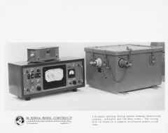
| Overall view of CU, MCU, and TU units. |
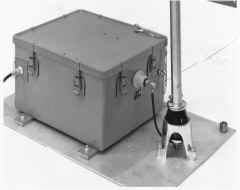
Un-numbered, showing CU attached to bottom of
TMC 35' whip antenna. |
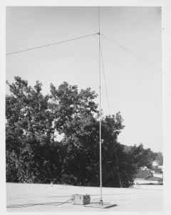
The ATS can be used with a wire antenna as
well, as shown here. |
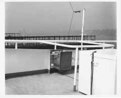
A typical installation on top of one of TMC's
Mamaorneck plants, employing a 35' whip. |
 |
 |
 |
|
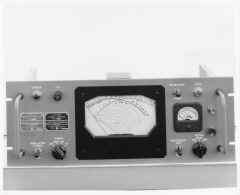
| 589.30-1 ATS-1 MCU front view. |
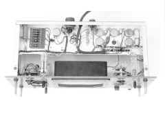
584.1--9. ATS-1 MCU bottom view. |
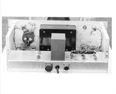
585.13-9. ATS-1 MCU rear view |
|
| |
 |
 |
 |
| I don't have an ATS-2 front view.. it'll show
up eventually! |
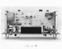
5810.8-7. ATS-2 MCU top view. I
believe, best I can tell, that this is an early production verwion of the
MCU-2. |
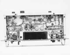
661.10-3. ATS-2 MCU top view.
This is the later production version of the MCU-2. |
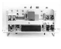
5911.6-25 MCU-2 bottom view. |
 |
 |
 |
|
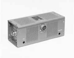
| 599.23-5. Overall view of CU-2
directional coupler. |
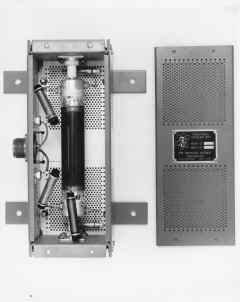
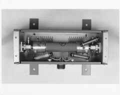
5911.6-13. Inside view of CU-2. |
655.6-6. Inside view of CU-2. |
|
 |
 |
 |
 |
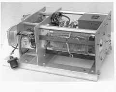
| 584.1-11. Components of TU-2 removed
from fiberglass box. |
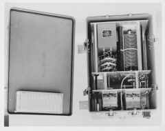
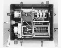
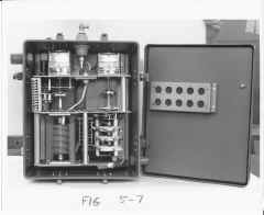
584.1-3. Inside view of TU-2. |
5912.15-5. Inside view of TU-2. |
5911.6-14. Another inside view of TU-2. |
 |
 |
 |
 |
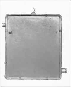
| 599.23-6. Top view of TU-2 fiberglass
box. |
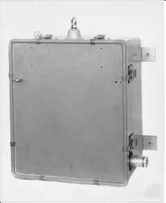
599,23-7. Overall view of fiberglass
box of TU-2. |
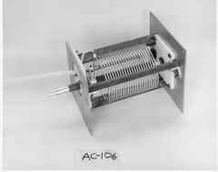
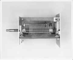
5911.6-10. AC-106 coil, part of TU-2. |
5910.1-9. Another view of AC-106. |
 |
 |
|
|
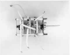
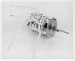
| 5910.1-10. Switch assembly in TU-2. |
5911.6-9. Another view of switch assy. |
|
|
| |
|
|
|
| |
|
|
|
